6. Distribution & DSP issues
The core functionality of a networked audio system is determined by the audio network protocol and its hardware to take care of the distribution of audio signals throughout the system, and Digital Signal Processors (DSP) to process (change) the audio signals. This chapter focuses on the core distribution and DSP functionality.
The sound quality of a networked audio system is not affected by the distribution system. A properly set up networked (or any digital) connection will transfer digital audio signals without changing the samples - the only function of a distribution system is to distribute, and not to process. The DSP hardware itself also does not affect the sound quality of a networked audio system - the internal processes in a DSP core can be regarded as distribution processes - moving samples to and from the DSP’s memory.
The DSP algorithms however do affect sound quality by definition - as the default status of a DSP algorithm is to just pass audio information from input to output without any change. Every change a DSP algorithm poses to an audio signal is therefore intended - it’s the most important part of a digital audio system’s Response.
The audio quality of a networked audio system on the other hand is not affected by the DSP algorithm - as all DSP algorithms are fully intended. Instead, only the bit depth and the sample rate of the distribution system and DSP hardware architecture affect the Performance of a system’s core functionality.

6.1 I/O distribution
If the bit depth of a networked audio system’s A/D and D/A converters is 24-bits, then of course the connection to and from the network also has to be at least 24-bits to preserve the 24-bit resolution. Most conventional digital audio formats such as AES3 (AES/EBU), AES10 (MADI), and Ethernet compliant audio network protocols such as EtherSound and CobraNet are 24-bit digital audio formats. All these formats are linear - they transport the digital audio samples without changing them. All digital audio formats therefore ‘sound’ the same. However, formats do differ in latency - with the Ethernet compliant audio protocols such as EtherSound, CobraNet and Dante posing a higher latency than the conventional point-to-point connection formats such as AES3 and AES10. The implications of latency differences in correlated signal paths are described in detail in chapter 5.6.
6.2 Interconnected DSP distribution
DSP MAC operations are performed at a bit depth higher than the 24 bit sampling bit depth to keep the accumulated quantization noise of rounding errors - generated with every MAC operation - below 24-bits. As most systems utilize multiple DSP chips, most DSP manufacturers support internal audio connections between DSP chips at a bit depth of 32 bits or more - reserving 8 or more bits for headroom and quantization noise to preserve a minimum resolution of 24 bits. If there is only one DSP device in the system, 24-bits are enough to connect to A/D converters and A/D converters in the system without loss of resolution.

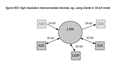
If multiple DSP devices have to be connected in a system using external digital audio formats, 24-bit formats can be used, but this will increase the system’s quantization noise above the 24-bit LSB level of -144dB. This is not a big problem if the signal path crosses such a connection only once - for example to connect to a digital speaker processor or a digital effect. But if a signal path uses the connection multiple times - for example in cascaded mixing consoles or in distributed free configuration DSP systems, the quantization noise might increase towards audible levels (above -120dBFS, inside the audio universe dynamic range as presented in chapter 4.2). To support high resolution interconnection of devices, some devices offer 32-bit interconnection, such as the CL and Rio series supporting Dante 32-bit mode(*6A).
6.3 Constant gain A/D converters
In digital audio systems with ‘constant gain’ to keep the digital levels constant if analogue gain is changed (see chapter 7.3), the A/D converter device has DSP built-in to adjust the digital gain before the audio signal is sent to the network. In such a system, analogue gain is dedicated to the function of driving the A/D converter at the most efficient level (with the lowest quantization noise floor), leaving digital gains in the DSP processes to manage mixing input levels fully independently from the analogue gain. When constant gain is activated, a certain headroom is reserved to allow for digital make-up of the analogue gain. Figure 604 presents constant gain level diagrams with a 6 dB safety headroom and +/- 12 dB make-up range, supporting +24 dB digital gain in the DSP receivers (eg. mixers). To provide the three extra bits required for the worst case situation make-up, the network must support at least 27 bits to allow the use of constant gain without a decrease in resolution. A 24-bit digital audio protocol could be used, but then only a worst case resolution of 21 bits can be supported.

6.4 DSP architecture
DSP hardware is available in many forms - usually in the form of devices that combine multiple DSP chips to make one DSP system. Chips can be generic microprocessors from manufacturers such as Intel or AMD, dedicated DSP chips from manufacturers such as Yamaha, Analog Devices, Motorola or Texas Instruments, or generic Field Programmable Gate Arrays (FPGA) offered by many manufacturers. In theory, any digital audio algorithm can be compiled for all of these platforms - the choice of DSP platform has no effect on the sound quality of an algorithm. However, the audio quality between DSP platforms and their implementations differ - with the main issues being DSP power, latency and bit depth.
DSP power
DSP power is the amount of processing available for MAC operations. Similar to the developments in the computer industry - with Moore’s law predicting a doubling of computing power every 1,5 years(*6B), DSP chips have developed to offer impressive amounts of DSP power, accommodating digital audio systems as a single DSP chip, as a combination of DSP chips connected through an internal data bus in a single device, or as a combination of DSP devices connected through an external data bus.
Latency
Digital audio processing such as mixing, compression, equalisation requires a certain amount of DSP power. Dedicated DSP chips perform operations in parallel, resulting in a very low latency per operation. The total latency of the system is then dependent on the number of operations required to perform the DSP processes in a signal chain - for example a channel strip in a mixing console. Native(*6C) systems - using generic microprocessors - perform MAC operations for all signal chains in the system one by one, causing much more latency. But because generic microprocessors have developed to very high speeds - mostly well above 1GHz - the latency of a powerful native system can be low enough to allow the use in live systems.
Bit depth
A signal that is processed in a DSP chip can include the results of many MAC operations - sometimes thousands when Infinite Impulse Response (IIR) or Finite Impulse Response (FIR) algorithms are used. As every MAC operation produces a result of double the resolution of the processed samples coming in from the processor’s data bus, the result has to be rounded before it can be written back - each time producing a rounding error (or quantization error). If there are thousands of MAC operations for a certain DSP process, these errors all add up to significant levels. To keep the accumulated error level outside of the audio universe (of 120dBFS), DSPs use a higher internal bit depth - normally 32 bits or more. Figure 605 presents a Yamaha DSP architecture with a 32-bit data bus and a 58-bit accumulator bit depth.

6.5 Fixed point vs floating point
For distribution of samples in a digital audio system, samples are normally represented by integer fixed point values with a certain bit depth. In DSP data buses however, often a floating point data format is used to allow a higher range of numbers to be used - implying a higher dynamic range. In a floating point representation, the available bits are divided in a mantissa - representing the value, and an exponent - representing the weight. In a 32-bit floating point representation such as used in many FPGA chips and native systems, 24 bits are used for the mantissa and 8 bits for the exponent, allowing for a ‘virtual 280-bit depth’ or ‘1,680 dB dynamic range’. For algorithm programmers this allows less strict programming compared to fixed point representation, as the limited dynamic range of fixed point 32 bits is no longer a constraint with complex processes using many MAC operations. However, there is a catch: the resolution of a floating point value is reduced with the bits needed for the exponent - in case of a 32-bit floating point representation, the resulting resolution of the mantissa is 24-bits at the best case, but even lower when levelling mistakes are made when programming or applying the algorithms. Figures 606A and 606B show a MAC operation in 32-bit fixed point and floating point representations that add a 32-bit -48 dBFS signal to a 32-bit -3 dBFS signal. The result in a floating point system has reduced the -48 dBFS input signal to 16 bits, while the fixed point representation still provides a 24-bit resolution.

Motorola(*6D) and Yamaha DSP’s have an internal DSP MAC operations bit depth of more than 56 or 58 bits - so for these DSP platforms the choice between fixed point and floating point is not very significant as the mantissa for a 56 bit or 58 bit value still has enough dynamic resolution to support algorithms with many MAC operations. Analog Devices SHARC (Super Harvard ARChitecture)(*6E) chips, Texas instruments(*6F) chips, FPGA chips and native DAW software and plug-ins can support both 32 bit and 64 bit floating point and fixed point modes, with some programmers using the 32-bit mode to offer a higher DSP power against lower costs. The issue is not significant if the programmer of the application used 64-bit mode, but both 32-bit fixed point and floating point modes pose dynamic range challenges to the algorithm programmer and sound engineer using the system. Fixed point systems support the highest resolution, but pose a risk of clipping: the algorithm programmer and the sound engineer have to constantly monitor the signal levels in the signal chain and take care that the level is below 0dBFS always. Floating point systems support a lower resolution with the risk of losing dynamic range of low level signals when mixed with high level signals, but there is never a risk of clipping in the floating point digital domain. In both cases, the sound engineer has to take care of the signal levels: in fixed point systems not to clip, in floating point systems not to lose dynamic range at low levels.
6.6 DSP user interfaces
When DSP algorithms are offered to a system’s sound engineer as variable processes (‘colouring tools’ in a natural sound system), the way the sound engineer applies the DSP algorithm is significantly affected by the provided user interface. This means that the Response of a system is affected not only by the system’s audio quality and sound quality, but also by the system’s user interface quality. As with sound quality, this brings up similar quality discussions: individual sound engineers often prefer different user interfaces. Applying the same DSP algorithm with different user interfaces will lead to different sound qualities depending on the user interface preferences of the sound engineer. In many cases where the same DSP algorithms are available in a range of devices with different sizes of user interfaces, sound engineers can improve the response of systems with compact user interfaces by realizing that the DSP algorithm offers the same response as the ones with more elaborate user interfaces.